I love Marlin Firmware.
What they have managed to squeeze into the 8bit 16mhz microcontrollers is impressive.
But what is even more impressive, is their documentation. The Marlin documentation is far and above anything I have seen for an open source project.
In addition to great documentation, they provide some very useful tools. Like the K-Factor Pattern Generator for calibrating Linear Advance in Marlin.
I wish Duet provided a similar tool, as I find it invaluable for calibrating your pressure advance settings.
What I have managed to do, is use the developer tools of the Chrome browser to edit the javascript and modify a few things to make it work.
Why go through such lengths?
Well, for a direct drive extruder the calibration values for duet are very low, and very sensitive.
how sensitive? I have found differences in value changes of 0.00002
And because I don't take "close enough" as an answer, I had to dig in and make the script fit the resolution I require.
At first I thought I'd download a copy of the marlin documentation source code and edit it that way. If you've looked at it, you'll find it's a lot of trouble to get the dev environment setup.
Instead, I found a hidden dev feature of Chrome that allows you to use a local copy of a file to overwrite the online version. But first, you need to enable it. Make sure you open up the K-Factor Pattern Generator first, then use the guide from Chrome to enable the local overrides.
Once you have enabled local overrides for the site, open up the dev tools, click on the sources tab on the top, and Page on the left and look for the k-factor.js file under tools/lin_advance folder.
Right Click on the k-factor.js and click Save For Overrides.
Open up the overrides tab and make sure the checkbox Enable Local Overrides is checked.
We're going to do two things. Change all of the 'M900 K' instances to 'M572 D0 S' and increase the precision to 5 points (by changing the Math.round10() occurances).
Click on the k-factor.js file and look for the lines that have M900 in them by using the search box.
The first occurrence should be (Line 266 on my version):
Next is (Line 458):
Next (Line 467):
Next (Line 487):
Now to increase the number of digits printed, search for createGlyphs
Line 292 on my version:
Now go back to your browser with the K-Factor Calibration page open, and enter in your settings, then click Generate G-Code.
I have found for PLA that the value is typically between 0.02-0.03
On my Aero the specific value is 0.02825
What they have managed to squeeze into the 8bit 16mhz microcontrollers is impressive.
But what is even more impressive, is their documentation. The Marlin documentation is far and above anything I have seen for an open source project.
In addition to great documentation, they provide some very useful tools. Like the K-Factor Pattern Generator for calibrating Linear Advance in Marlin.
I wish Duet provided a similar tool, as I find it invaluable for calibrating your pressure advance settings.
What I have managed to do, is use the developer tools of the Chrome browser to edit the javascript and modify a few things to make it work.
Why go through such lengths?
Well, for a direct drive extruder the calibration values for duet are very low, and very sensitive.
how sensitive? I have found differences in value changes of 0.00002
And because I don't take "close enough" as an answer, I had to dig in and make the script fit the resolution I require.
At first I thought I'd download a copy of the marlin documentation source code and edit it that way. If you've looked at it, you'll find it's a lot of trouble to get the dev environment setup.
Instead, I found a hidden dev feature of Chrome that allows you to use a local copy of a file to overwrite the online version. But first, you need to enable it. Make sure you open up the K-Factor Pattern Generator first, then use the guide from Chrome to enable the local overrides.
 |
| Opening the developer tools for Chrome |
Once you have enabled local overrides for the site, open up the dev tools, click on the sources tab on the top, and Page on the left and look for the k-factor.js file under tools/lin_advance folder.
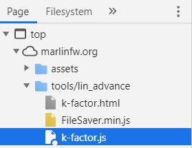 |
| k-factor.js on the marlin site |
Right Click on the k-factor.js and click Save For Overrides.
Open up the overrides tab and make sure the checkbox Enable Local Overrides is checked.
 |
| Editing the k-factor.js file |
Click on the k-factor.js file and look for the lines that have M900 in them by using the search box.
The first occurrence should be (Line 266 on my version):
'M900 K0 ; Set K-factor 0\n' +'M572 D0 S0 ; Set K-factor 0\n' +Next is (Line 458):
gcode += 'M900 K' + Math.round10(i, -3) + ' ; set K-factor\n' +gcode += 'M572 D0 S' + Math.round10(i, -5) + ' ; set K-factor\n' +Next (Line 467):
gcode += 'M900 K' + Math.round10(i, -3) + ' ; set K-factor\n' +gcode += 'M572 D0 S' + Math.round10(i, -5) + ' ; set K-factor\n' +Next (Line 487):
gcode += 'M900 K' + Math.round10(i, -3) + ' ; set K-factor\n' +gcode += 'M572 D0 S' + Math.round10(i, -5) + ' ; set K-factor\n' +Now to increase the number of digits printed, search for createGlyphs
Line 292 on my version:
createGlyphs(numStartX, numStartY + (stepping * LINE_SPACING), basicSettings, Math.round10(i, -3)) +createGlyphs(numStartX, numStartY + (stepping * LINE_SPACING), basicSettings, Math.round10(i, -5)) +Now go back to your browser with the K-Factor Calibration page open, and enter in your settings, then click Generate G-Code.
I have found for PLA that the value is typically between 0.02-0.03
On my Aero the specific value is 0.02825
Comments
Post a Comment