You ever want to take apart something prohibitively expensive and find out what's inside? I do, all the time.
Lucky for me this cast aluminum massager is broken (it won't turn off).
So I get to try to fix it (hopefully). It's likely just a bad mosfet. But it'd be fun to upgrade.
 It's surprisingly low power. 19.5W, 13v @ 1.5A
13v is a bit strange to see, but whatever. Could very likely be replaced by a 12v supply without significant loss in power.
It's surprisingly low power. 19.5W, 13v @ 1.5A
13v is a bit strange to see, but whatever. Could very likely be replaced by a 12v supply without significant loss in power.
 One screw came out halfway and appears to stop. Maybe it has a retaining clip? The other at the end won't budge. Time for a bigger screwdriver.
 It took a bit of prying. The retaining ring is glued on (I was worried it was screwed on). A bit of wiggling and it's free.
The screw that I thought had a retaining clip actually has a screw standoff to hold the PCB in. I might try to take them apart, but it's not necessary to.
It took a bit of prying. The retaining ring is glued on (I was worried it was screwed on). A bit of wiggling and it's free.
The screw that I thought had a retaining clip actually has a screw standoff to hold the PCB in. I might try to take them apart, but it's not necessary to.

 And now for what you've all been waiting for.
It's an incredibly simple PCB. For the price I was expecting more. There is nothing stopping this from being sold for under $100
The switches are membrane. Membrane! C'mon! That's not cool.
I'll get to looking at the circuit in a bit.
And now for what you've all been waiting for.
It's an incredibly simple PCB. For the price I was expecting more. There is nothing stopping this from being sold for under $100
The switches are membrane. Membrane! C'mon! That's not cool.
I'll get to looking at the circuit in a bit.

 We have two main chips, two mosfets, and a pinch of other components.
Disappointing is the best way I can put it. Those mosfets are TINY. What are these, mosfets for ants?! No wonder it burned out.
We have:
12F1501 8bit PIC microcontroller w/ 1K rom 64b ram
78L05 5v 100ma VR
We have two main chips, two mosfets, and a pinch of other components.
Disappointing is the best way I can put it. Those mosfets are TINY. What are these, mosfets for ants?! No wonder it burned out.
We have:
12F1501 8bit PIC microcontroller w/ 1K rom 64b ram
78L05 5v 100ma VR


 One mosfet is for the LEDs. When you press the power button the microcontroller lights up the LEDs. Meaning: it's always on and powered.
Each button gets a GPIO pin, and each MOSFET too. Nothing fancy here.
Took the time to draw the schematic.
Like I said really simple. I don't understand what L3 is doing here.
I'm trying to think of how the Mosfet driver circuit can be modified so that the it doesn't burnout again. AFAIK This is pretty much exactly what you would want as protection
One mosfet is for the LEDs. When you press the power button the microcontroller lights up the LEDs. Meaning: it's always on and powered.
Each button gets a GPIO pin, and each MOSFET too. Nothing fancy here.
Took the time to draw the schematic.
Like I said really simple. I don't understand what L3 is doing here.
I'm trying to think of how the Mosfet driver circuit can be modified so that the it doesn't burnout again. AFAIK This is pretty much exactly what you would want as protection
 The next piece of the puzzle is the PCB Layout. There are 4 mounting holes for the membrane switch pad, and 2 M3 pcb mounting holes. The overall PCB is 23mm x 88mm with a taper down to 13mm at the end.
However, you are not limited to that size.
The purple outline is the max safe.
The next piece of the puzzle is the PCB Layout. There are 4 mounting holes for the membrane switch pad, and 2 M3 pcb mounting holes. The overall PCB is 23mm x 88mm with a taper down to 13mm at the end.
However, you are not limited to that size.
The purple outline is the max safe.
 Time to move on to the motor.
There are no markings on it, so we don't know the specs.
It is 35.5mm in diameter and 50mm long, and has a 1/8inch diameter shaft.
It turns out this is a standard known as 540. There happen to be a lot of drop in replacements at this size.
Time to move on to the motor.
There are no markings on it, so we don't know the specs.
It is 35.5mm in diameter and 50mm long, and has a 1/8inch diameter shaft.
It turns out this is a standard known as 540. There happen to be a lot of drop in replacements at this size.
 The motor is characterized as pictured.
920-934uH at 2 ohms with 100hz Test.
This decreases to 840uH @ 2.7ohm at 1kHz.
What does that mean?
I don't know, I'm not a motor or inductance person. But I think we can calculate the speed somehow.
The motor is characterized as pictured.
920-934uH at 2 ohms with 100hz Test.
This decreases to 840uH @ 2.7ohm at 1kHz.
What does that mean?
I don't know, I'm not a motor or inductance person. But I think we can calculate the speed somehow.
 Why not go all the way, right?
The weight is much smaller than I thought it would be. And unfinished castings.
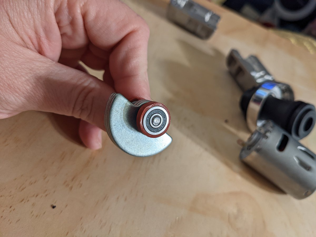
It has two bearings in the head. A bit of rubber surrounds them.
The motor attaches to the head through a flex shaft. Not even clamped, but it could be glued.
Why not go all the way, right?
The weight is much smaller than I thought it would be. And unfinished castings.
It has two bearings in the head. A bit of rubber surrounds them.
The motor attaches to the head through a flex shaft. Not even clamped, but it could be glued.

 The motor has been liberated! It wasn't glued!
The motor shaft is 12.5mm long. The shaft for the weight appears to be threaded on one end. It's all press-fit on there. You're not going to replace those bearings easily.
The motor has been liberated! It wasn't glued!
The motor shaft is 12.5mm long. The shaft for the weight appears to be threaded on one end. It's all press-fit on there. You're not going to replace those bearings easily.


 It was recommended to me on Twitter to use Audacity to try to get the speed of the motor.
It is tricky to do!
We have peaks at:
226
452
676
920
1132 & 1249
My best guess is 226hz is our speed.
Calculated out to 226*60 = 13,560RPM
It was recommended to me on Twitter to use Audacity to try to get the speed of the motor.
It is tricky to do!
We have peaks at:
226
452
676
920
1132 & 1249
My best guess is 226hz is our speed.
Calculated out to 226*60 = 13,560RPM
 That's it for now. but I have plans...
Brushless motors with integrated ESC...
That's it for now. but I have plans...
Brushless motors with integrated ESC...
 You can get the PCB Layout and Schematics here: My Github


Comments
Post a Comment